
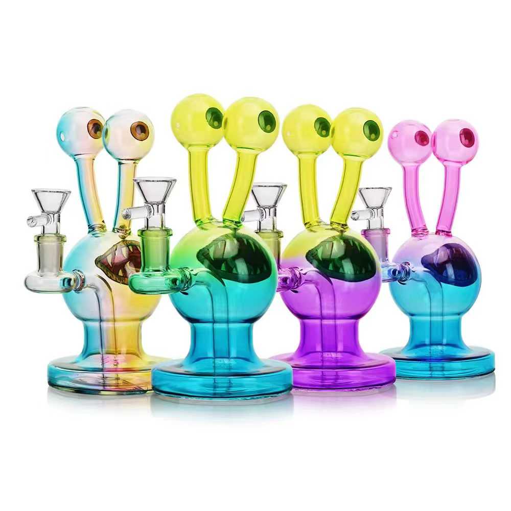
Every buyer who has ever brought an ambitious custom glass pipe design to a manufacturer knows the sinking feeling: the drawing looked perfect on screen, but the factory says it cannot be built as drawn. The gap between a concept sketch and a shippable, structurally sound borosilicate glass piece is where most OEM projects stall, and the root cause is almost always the same — a failure to account for glass manufacturing limits early enough in the process.
Understanding those limits before you commit tooling budget is the single most valuable thing a brand owner can do. This guide walks through the constraints that cause custom designs to fail, why they exist, and how an experienced OEM partner like Elfglass, whose production workflow is documented step by step here, catches them before they become expensive mistakes.
Wall Thickness: The Constraint That Overrides Everything
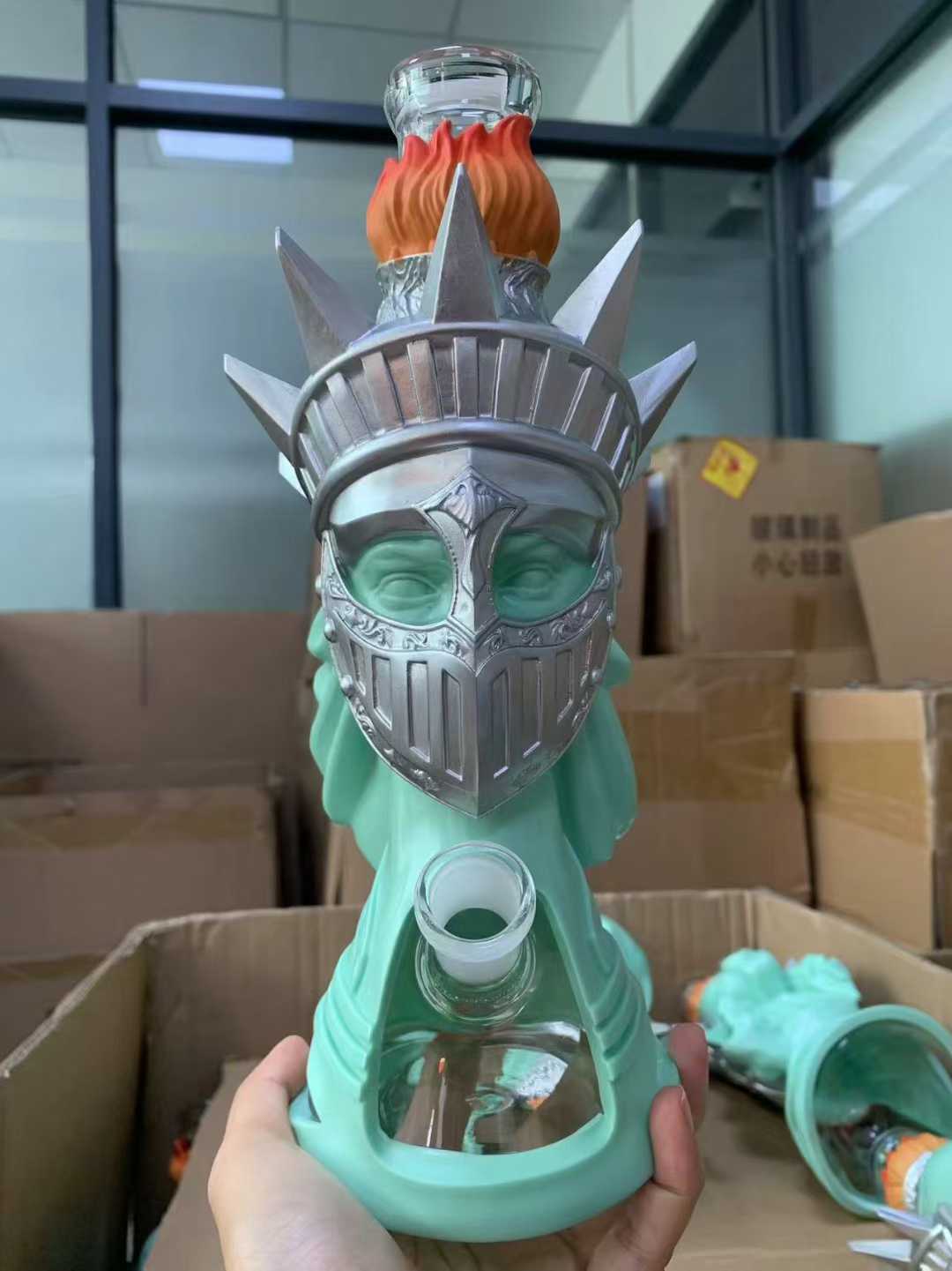
Glass is not injection-moulded plastic. You cannot simply specify any wall dimension and expect the material to comply. In borosilicate glass pipe manufacturing, wall thickness is governed by the physics of hand-blown glassworking, and it is the number-one reason custom designs fail when they reach the production floor. These forming limits match the working behavior of hot glass documented in the long craft literature on glassblowing, which is why some shapes resist automation.
Most glass pipes require a minimum wall thickness of 2 to 3 millimetres to survive the annealing cycle and remain durable enough for daily use. Go thinner than that, and the glass becomes fragile during the cooling phase. Micro-cracks form as the outer surface contracts faster than the inner mass. Those cracks may not be visible immediately, but they propagate under thermal cycling and mechanical stress, turning a beautiful prototype into a warranty liability six months down the line.
On the other end of the spectrum, walls that are too thick create their own problems. Borosilicate glass cools from the outside in. A section that is significantly thicker than the surrounding structure will retain heat longer, creating differential cooling rates across the piece. The result is internal stress that no amount of annealing can fully relieve. The piece may pass initial inspection but fail weeks later in the field, or worse, crack during the annealing lehr itself.
The practical rule is consistency. Designs that maintain relatively uniform wall thickness across the entire piece will always produce better results than designs with dramatic transitions. If your concept calls for a paper-thin decorative section adjoining a thick structural joint, that transition zone is where failure will originate. A competent manufacturer will flag this during the design review and suggest adjustments that preserve the visual intent while keeping the glass within workable parameters.
Joint Angles and Connection Geometry
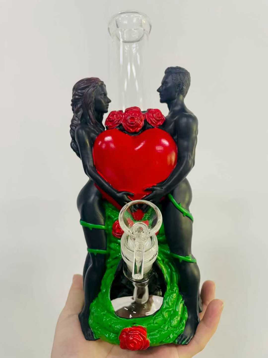
Glass pipe designs frequently involve multiple chambers, percolators, and attachment points that meet at various angles. On a CAD model, a 30-degree joint connecting a downstem to a main chamber looks clean and precise. In the glassblower’s hands, that same joint is one of the most difficult features to execute reliably.
The core issue is that glass tubing and connections are formed while the material is in a viscous, molten state. The glassblower shapes joints by heating, bending, and fusing. Sharp internal angles — anything below roughly 45 degrees on an internal chamber connection — create thin spots at the apex of the bend where the glass stretches beyond its safe working range. Those thin spots become the weakest points in the entire piece.
External joint angles present different challenges. A joint that angles sharply outward may require the glassblower to pull and shape the glass in a direction that works against gravity and the natural flow of the material. The result is either an inconsistent wall at the joint or a connection that looks correct from one angle but has a visible deformity when rotated. Both outcomes fail quality control.
This is why manufacturers often recommend increasing joint angles or redesigning the connection geometry rather than attempting to reproduce an exact CAD angle. The adjustment is usually small — a few degrees of change — but it dramatically improves the success rate during production. If you are preparing a design brief, this is exactly the kind of technical feedback that separates a factory with real production experience from one that simply says yes to everything and delivers a container of cracked units. The article on how to write a glass pipe design brief covers how to communicate joint specifications in a way that gives the factory enough information to propose workable alternatives.
Percolator Complexity: Where Ambition Meets Reality
Percolators are the feature that most often separates a marketable product from a manufacturing nightmare. Buyers love them because they differentiate products on the shelf. Glassblowers respect them because each additional percolator stage adds exponential complexity to the build.
A single-chamber percolator with straightforward slits or holes is well within standard manufacturing capability. The problems begin when designs call for multi-chamber percolators, matrix-style perc arrays, or intricate honeycomb structures with dozens of small-diameter passageways packed into a confined space. Each of these features multiplies the number of individual glass-to-glass fusions required, and every fusion is a potential failure point.
The specific glass manufacturing limits around percolators come down to three factors. First, the diameter of individual holes or slits must remain large enough to maintain airflow while being small enough to create the desired diffusion effect. Holes below approximately 2 millimetres in diameter are prone to blockage from glass residue during the fusing process and are nearly impossible to clean after production. Second, the spacing between adjacent holes must account for the structural integrity of the glass between them. Pack holes too closely, and the thin glass walls between them crumble during annealing. Third, the overall length of a multi-perc stack increases the leverage on each joint, making the assembly more vulnerable to breakage during handling, packing, and shipping. Forming limits described here follow the manufacturing constraint model, where material physics sets hard boundaries on achievable geometry.
The practical approach is to work with your manufacturer to find the simplest percolator configuration that delivers the functional performance you need. Often, a well-designed dual-chamber setup outperforms a four-chamber design that is structurally compromised. This kind of value engineering is a core part of the OEM versus ODM decision process — knowing when to simplify without sacrificing the user experience.
Mold Limitations and What They Mean for Your Design
Not every glass pipe component is free-blown. Many designs use molds to form consistent shapes, especially for production runs where uniformity across hundreds of units matters. But molds introduce their own set of glass manufacturing limits that designers need to understand.
The mold material — typically graphite or steel — must withstand repeated exposure to molten borosilicate glass at temperatures exceeding 1,600 degrees Celsius. Over time, the mold surface degrades. This degradation is gradual and may not be noticeable in the first dozen pieces, but by the fiftieth unit, surface imperfections in the mold translate to subtle defects in the glass. For a 100-piece minimum order, this means the last pieces in the run may differ slightly from the approved sample.
Undercut geometries are another mold constraint that catches designers off guard. In injection moulding, you can design complex undercuts and use slide mechanisms to release the part. Glass molds do not have slides. Any feature that creates an undercut — a lip that curves inward, a recess that narrows below its opening — cannot be released from a standard glass mold without breaking either the mold or the piece. If your design includes undercuts, it either needs to be redesigned for mold release or moved to a free-blown process, which changes the cost structure and consistency profile entirely.
At Elfglass, custom molds are built exclusively for each client, which means the mold is designed with production feasibility in mind from the start. The sample revision process exists precisely to validate that the mold produces pieces matching the approved design before bulk production begins. Skipping sampling to save time or money is the most common way buyers discover mold limitations the hard way — with a full production run that does not match expectations.
Annealing and Thermal Stress: The Invisible Failure
Annealing is the process where glass is slowly cooled in a temperature-controlled kiln to relieve internal stresses. It is not a optional finishing step — it is the step that determines whether the piece survives its first month of use. And it is where many custom designs fail in ways that are invisible until the product reaches the end user.
Every feature you add to a glass pipe — a joint, a perc, a decorative twist, a colour frit infill — creates a zone where the glass mass changes. These mass changes mean different cooling rates during annealing. A thin section cools quickly while the adjacent thick section retains heat. The boundary between them becomes a stress concentration. If the stress exceeds the glass’s tensile strength, the piece cracks. Sometimes this happens in the annealing lehr. Sometimes it happens on the retail shelf. Sometimes it happens in the consumer’s hands three months after purchase.
The annealing constraint has direct implications for design. Pieces with complex geometries need longer annealing cycles, which increases production time and cost. Designs that combine thick and thin sections in close proximity may need structural modifications — additional glass mass at transition points, or redesigned features that distribute the glass more evenly. These modifications are not compromises to the design; they are engineering decisions that make the difference between a product that lasts and one that generates returns.
This is also why the rapid sample turnaround workflow matters so much. A sample that goes through the full annealing cycle reveals thermal stress issues before you commit to bulk production. If the sample cracks during cooling, you know the design needs adjustment. Catching that in sampling costs a few days. Catching it after 500 pieces come off the line costs thousands of dollars.
Turn Your Concept Into Production-Ready Glass
Elfglass takes you from design brief and CAD/STEP files to prototyping, branding, and mold exclusivity, with your IP protected by NDA. Send us your concept and we will return a manufacturable plan and quote.
MOQ from 100 pieces | BSCI / WRAP / ISO 9001 | NDA before every project
Enclosed Structures and Access Limitations
Some custom designs call for fully enclosed chambers, sealed decorative elements, or internal structures that cannot be accessed after the glass is fused. These features are theoretically possible but practically fraught. The fundamental problem is that enclosed structures trap heat during the glassworking process. Gas expansion inside a sealed chamber can cause the piece to burst from the inside out during firing. Conversely, if the enclosed space is not perfectly sealed, contaminants enter during production and create visible defects that cannot be cleaned.
Multi-chamber designs where internal walls separate different sections also present annealing challenges. Each internal wall creates additional thermal mass differentials. The more chambers, the more complex the annealing profile must be, and the higher the probability that one section will cool at a different rate than the others. For production runs, this complexity translates directly into a higher reject rate, which means higher per-unit costs and longer lead times.
The recommendation from a manufacturing standpoint is to keep enclosed structures as simple as possible. A single sealed decorative air bubble is well within capability. A multi-chamber enclosed system with internal passageways requires careful engineering and should always be prototyped through multiple sample iterations before committing to production. The design files factories need article explains exactly what technical documentation helps the factory evaluate these features accurately before sampling begins.
Surface Treatments and Their Interaction with Form
Custom designs often incorporate surface treatments — logo printing, etching, sandblasting, or colour frit application. These treatments are applied after the primary glass forming process, but they interact with the form in ways that affect manufacturability. A design that looks straightforward until you consider how the surface treatment will be applied can stall an entire project.
Sandblasting, for instance, requires line-of-sight access to the surface being treated. If your design has recessed areas, deep grooves, or internal chambers with openings that face away from the blast nozzle, those areas will not receive uniform treatment. The result is a patchy, inconsistent finish that fails quality control. Similarly, pad printing requires a flat or gently curved surface. Printing on a compound curve — a surface that curves in two directions simultaneously — produces distorted logos that look unprofessional.
The article on glass logo printing, etching, and sandblasting details the specific requirements for each surface treatment method. The key takeaway for custom design is that the form must accommodate the finishing process. If you are designing a piece with extensive surface decoration, consider how each treatment will be physically applied and inspected before finalizing the geometry.
The Communication Gap: Where Designs Actually Die
Technical constraints like wall thickness, joint angles, and percolator complexity are real, but they are solvable. The factor that causes more custom design failures than any physical limitation is poor communication between the buyer and the factory. A design brief that is vague about dimensions, ambiguous about tolerances, or silent about the intended use case will produce manufacturing failures regardless of how skilled the glassblowers are.
Ava Zeng, founder of Elfglass, puts it directly: “What kills a great idea is never the technology, but the communication gap and a lack of empathy.” That statement reflects fifteen years of watching promising projects fail not because the design was impossible, but because the factory did not fully understand what the buyer needed, and the buyer did not understand what the factory needed to know.
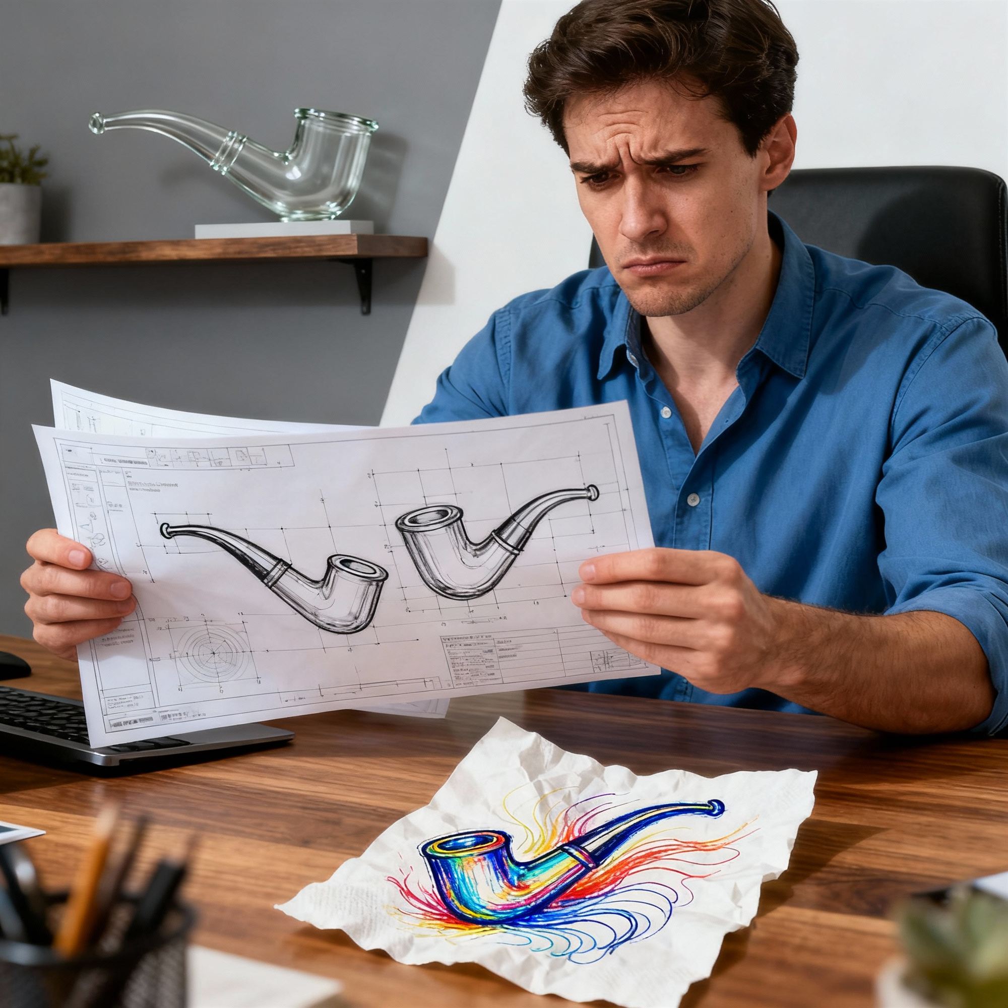
Consider a common scenario. A buyer sends a sketch of a glass pipe with a specific percolator configuration. The sketch shows the general idea but does not specify hole diameter, wall thickness at the perc junction, or the acceptable tolerance for joint angle variation. The factory, eager to move forward, makes assumptions about each of these parameters and produces a sample. The sample looks close to the sketch but does not match the buyer’s unstated expectations. The buyer rejects it. The factory is confused. Two or three revision cycles later, both parties are frustrated, the timeline is blown, and the project may never recover.
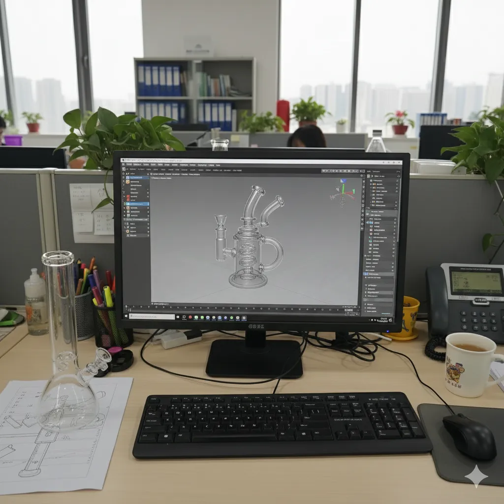
This is why Elfglass structures its OEM process around Day 1 consultation, where every design brief is reviewed in detail before any physical work begins. By Day 2, a 3D model is produced that makes all dimensions explicit. By Day 3 through 7, sampling validates the design against real-world manufacturing conditions. The entire process is designed to surface and resolve communication gaps before they become physical failures. An NDA is signed before every project begins, so buyers can share proprietary design details freely during this consultation phase.
Practical Steps to Keep Your Custom Design Manufacturable
Understanding glass manufacturing limits is only useful if it changes how you approach the design process. Here are the practical steps that experienced buyers follow to keep their custom designs within manufacturable parameters.
Start with the manufacturing constraints, not the concept sketch. Before you finalize a design, review the wall thickness requirements, joint angle limitations, and percolator spacing rules outlined above. Build those constraints into your initial concept rather than discovering them after the first sample fails.
Provide complete technical documentation. A sketch on a napkin is a conversation starter, not a design brief. Your submission should include exact dimensions, wall thickness specifications, joint angles, percolator hole sizes and spacing, and any surface treatment requirements. The more precise your documentation, the fewer assumptions the factory needs to make, and the closer the first sample will be to your vision.
Budget for at least one revision cycle. Even with perfect documentation, the first sample rarely matches the final vision exactly. Glass is a hand-worked material, and subtle variations are normal. Plan your timeline and budget to accommodate one or two revision rounds. At Elfglass, sampling takes 1 to 3 days, and the sample revision process is designed to be fast and iterative.
Visit the production floor if possible, or at minimum, request video documentation of the sampling process. Seeing how your design is actually built gives you intuition about manufacturing constraints that no written guide can provide. It also builds the relationship with the production team, which pays dividends when you need fast turnaround on a complex order.
Choose your manufacturer based on their willingness to say no. A factory that approves every design without question is not saving you time — it is storing up problems for later. The best manufacturing partners push back on designs that will not work, explain why, and propose alternatives that preserve your design intent. That pushback is a sign of expertise, not obstruction.
When Limits Become Opportunities
There is a counterintuitive truth in custom glass manufacturing: constraints often produce better designs than unlimited freedom. When a designer knows that wall thickness must stay within a certain range, they find creative ways to achieve visual impact within that range. When joint angles are limited by physics, the design develops a distinctive aesthetic that reflects the material’s natural behaviour rather than fighting against it.
Some of the most commercially successful glass pipe designs on the market are those that embrace the material rather than forcing it into shapes it was never meant to hold. The brands that thrive are the ones that treat their manufacturer as a design partner, not just a pair of hands that turns drawings into products. Browse the wholesale hand pipes collection for designs that work with the material instead of against it.
Elfglass operates under the principle captured in its brand slogan — “A Manufacturer With the Soul of a Designer” — because the distinction between manufacturing and design has always been artificial in glass work. The glassblower shaping your piece is making hundreds of micro-decisions about form, thickness, and flow that directly affect the final product. When those decisions are guided by a shared understanding between buyer and maker, the result is a product that is both beautiful and buildable.
If you have a custom design that you want to evaluate against real-world manufacturing constraints, the next step is a direct conversation. Reach out to the Elfglass team with your design files or concept sketches. With quote responses within 12 hours and a structured OEM process that moves from consultation to 3D design in a single day, you will know whether your concept is manufacturable before the week is out. The factory operates 1,000 square metres of production space with 20 employees and a monthly capacity of 10,000 pieces, with a minimum order of 100 pieces per design. Sampling takes 1 to 3 days, bulk production runs 7 to 12 days, and every project begins with an NDA so your intellectual property stays protected throughout the process. For a deeper look at how to safeguard your designs when sourcing overseas, the guide on protecting product design IP when sourcing overseas covers the legal and practical steps every brand should take.
For a detailed comparison, see our guide on glass pipe wholesale pricing factors.
Frequently Asked Questions
Why do custom glass pipe designs fail in manufacturing?
Custom designs most commonly fail due to wall thickness that falls outside the 2 to 3 millimetre safe range, joint angles that create thin spots at bends, or percolator complexity that exceeds what hand-blown glass techniques can achieve reliably at production scale.
What is the minimum wall thickness for borosilicate glass pipes?
Most glass pipes require a minimum wall thickness of 2 to 3 millimetres to maintain structural integrity during the annealing process and throughout normal consumer use. Thinner walls risk micro-cracking and thermal stress failure.
How does Elfglass handle design feasibility assessment?
Elfglass reviews every design brief on Day 1 of the OEM process, produces a 3D model by Day 2 that makes all dimensions explicit, and flags any manufacturing constraints before sampling begins. This front-loaded review prevents costly revisions later in the production cycle.
Can any glass pipe design be manufactured with the right equipment?
Most designs can be manufactured with appropriate adjustments. However, extremely thin walls below 2 millimetres, fully enclosed multi-chamber structures, or sharp internal angles below 45 degrees may require design modifications to be producible at scale with acceptable quality.
What is the sampling timeline for a custom glass pipe design?
At Elfglass, sampling takes 1 to 3 days after design confirmation. The full OEM process moves from initial consultation on Day 1 to 3D modelling on Day 2, sampling between Day 3 and Day 7, and delivery of approved production orders within 15 days.
About the Author
Ava Zeng is the founder of Elfglass, a Shenzhen-based borosilicate glass pipe manufacturer serving B2B brands worldwide. Every guide on this site is grounded in her production-floor experience— the annealing lines, QC checkpoints, and export orders behind each claim.
Before you commit to a supplier, read her founder’s story and trust promise, and the guide to vetting a reliable glass pipe manufacturer— the same red-flag checklist Elfglass applies to its own suppliers.
Ready to Source Custom Glass Pipes?
Get a free quote within 24 hours. MOQ from 100 pieces. NDA-protected design consultation.
